Download Part Print Dimensions
Press F11 and create layer and name it solid
Press Alt+Enter to open Property Manager
Click on solid
Change layer of solid to solid layer
Press F11

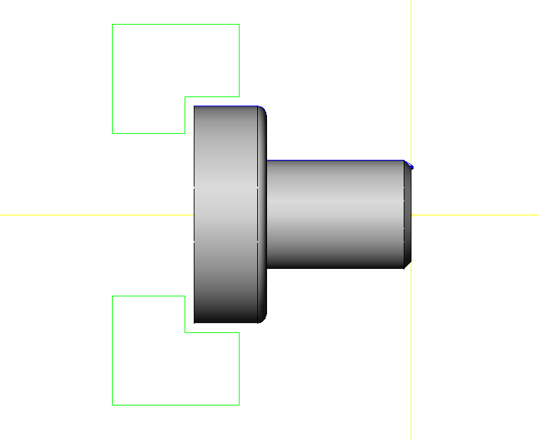
Look at the bottom right of your screen.

Make sure Grid is off and Highlight is on.

Left click face geometry then left click for “yes”
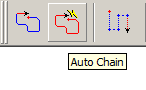
Go to Create Features (blue outline)

Left click Autochain (red racetrack)
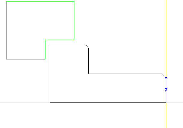
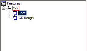
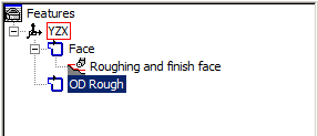
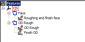
Press F2 to open Features window

Left click 1 Chain and right click and rename to Face.
Drag window over OD geometry.

Click Autochain and rename the chain OD rough.
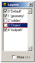
Create Layer and name it Toolpath.
Left click on your face chain feature.
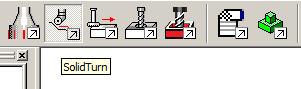
Click on solid turn
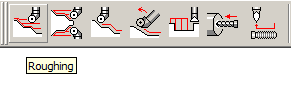
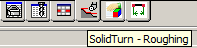
Click on Roughing.
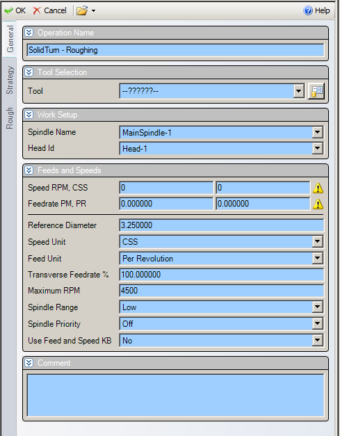
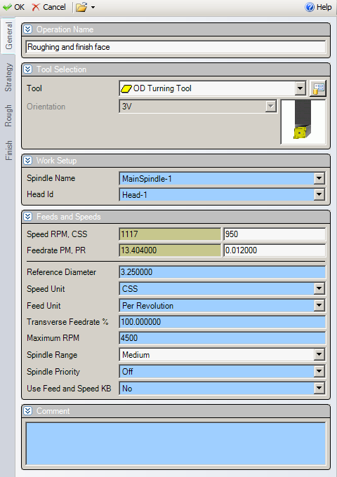
The following window will appear.
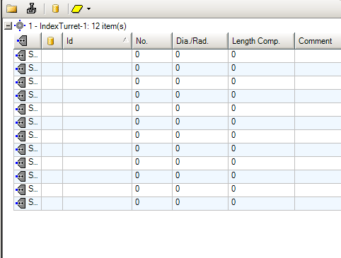
At the bottom of the window click on the Tools button.
The following window will appear.
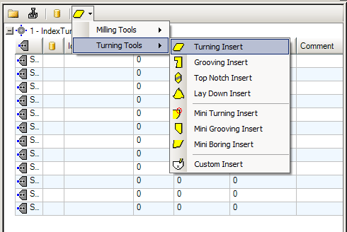
Click on the yellow insert button
Go to Turning Tools and then turning insert
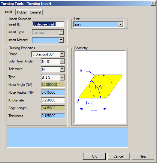
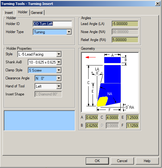
The following window will appear.
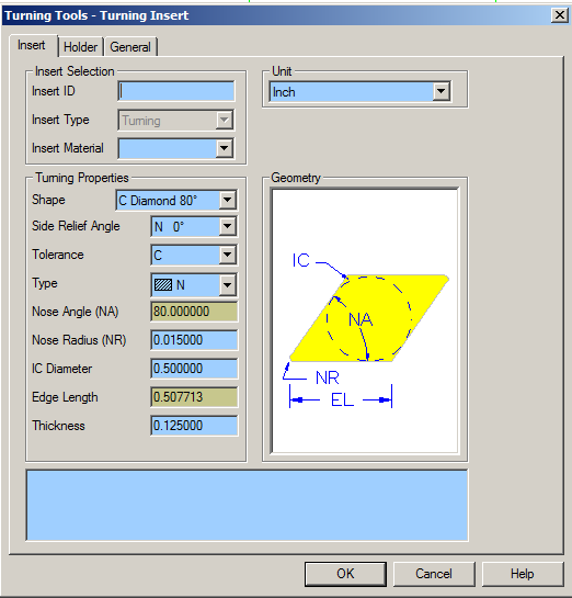
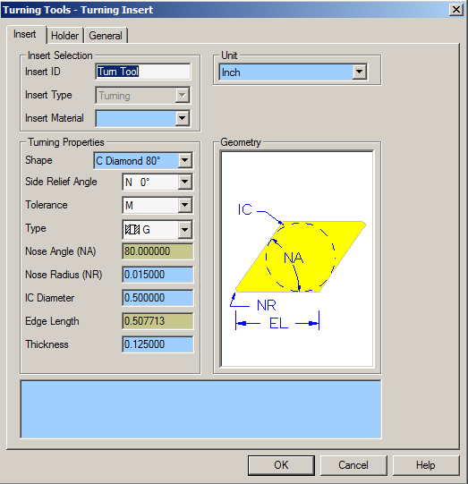
Enter the following information.
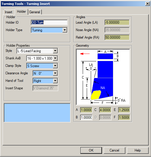
Select the Holder tab and enter the following information.
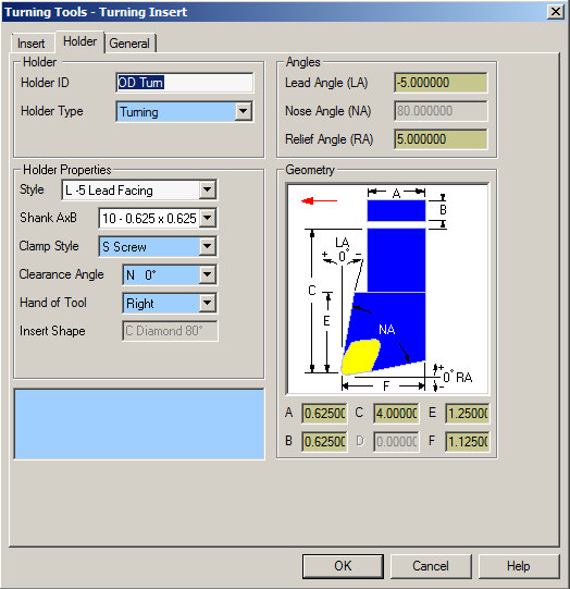
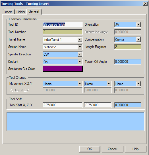
Select the General tab and enter the following information.
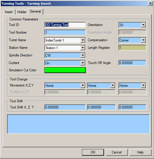
Click Ok.
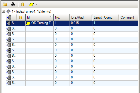
Notice the tool in your tool window.
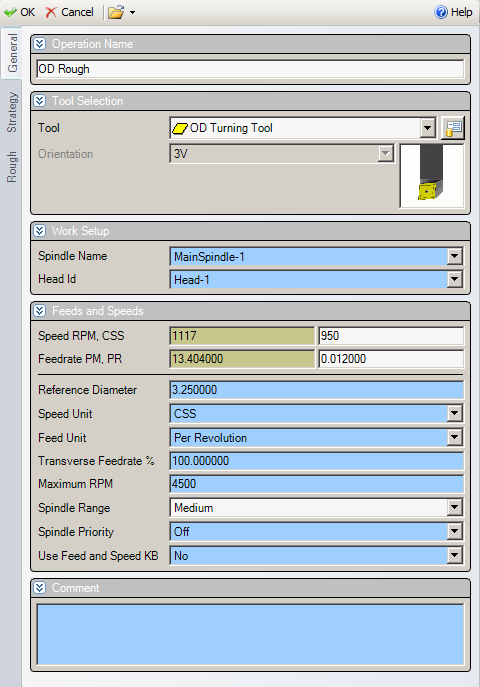
Return to the Solidturn- Roughing tab.
Enter the following information.
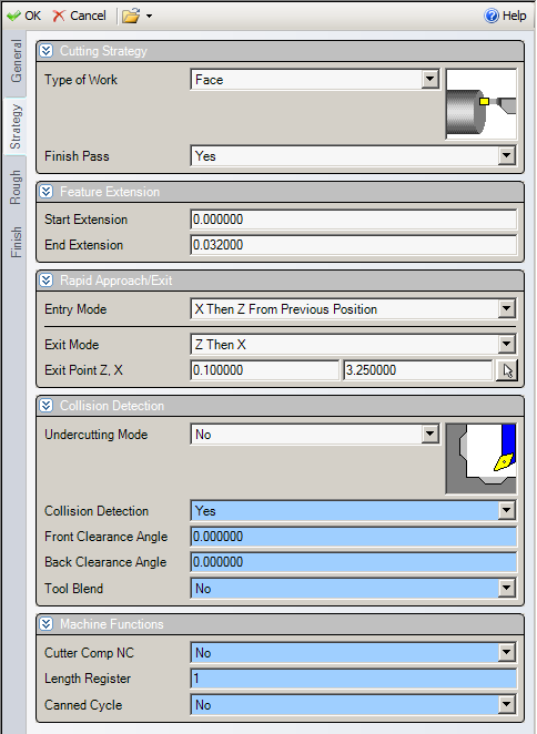
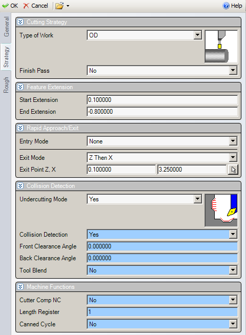
Select the Strategy tab.
Enter the following information.
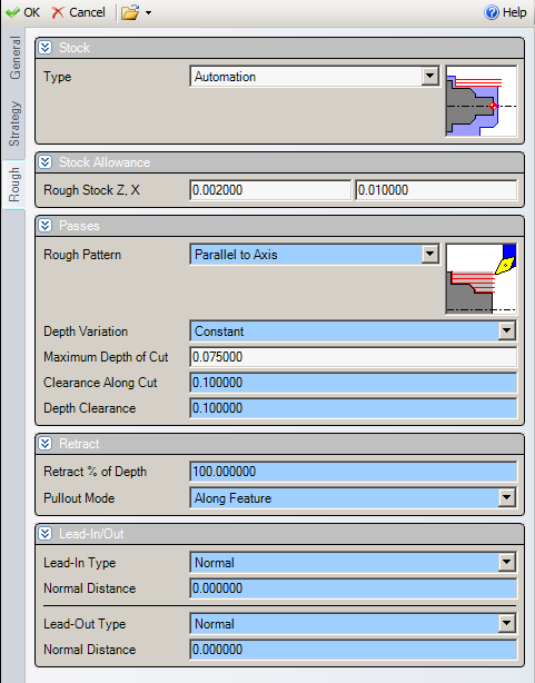
Select the rough tab.
Enter the following information
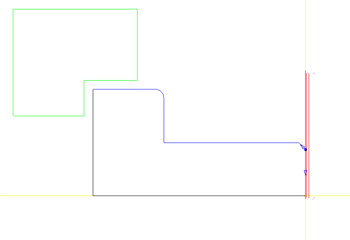
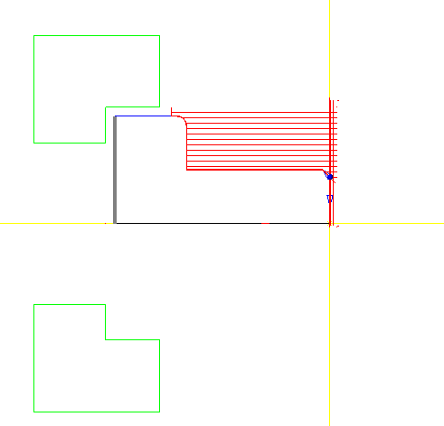
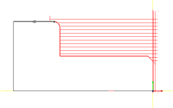
Click Ok and notice the facing toolpath. (red lines)
Within the Features window, select the tools tab.
Select the add new turning tool insert button and add a too with the following information.
Click OK
Return to your Features tab and select your OD Rough chain.
Now click your Roughing operation.

Enter the following information.

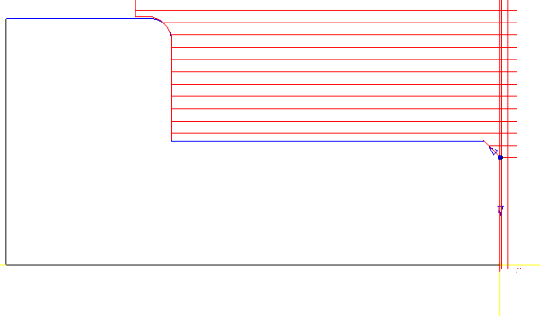
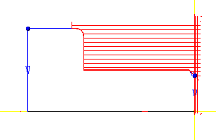
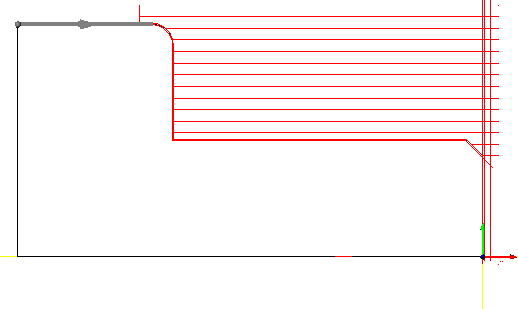
Click Ok and notice the gererated toolpath.
Now select your OD Rough Chain again.

Click on Contour on your Solidturn toolbar.

Notice the window that appears in your Features window.
Enter the following information.

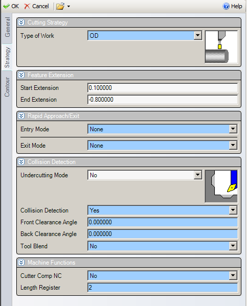
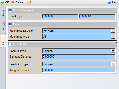
Click Ok.
Click on the top of your Features List to highlight Features.
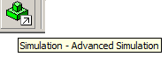
On your Smart toolbar click the Simulation button.
Now press play
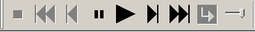
Now Press Stop to go back to the main screen.

Sub Spindle 2nd Op
Now go back to Solidturn on your Smart Toolbar.

Now click Pick up

Enter the following information.
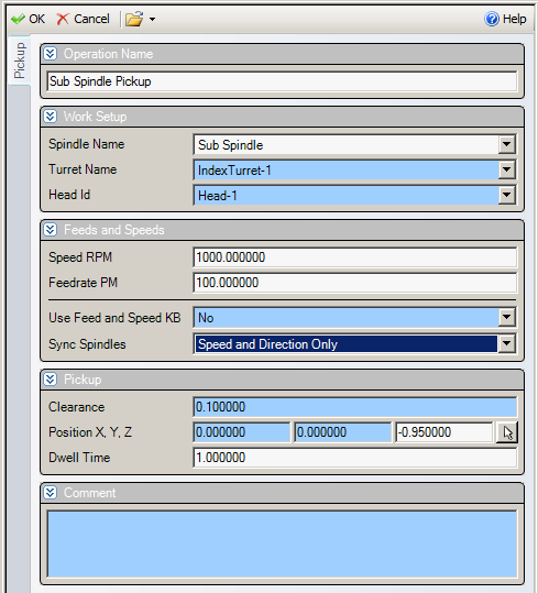
Press Ok.
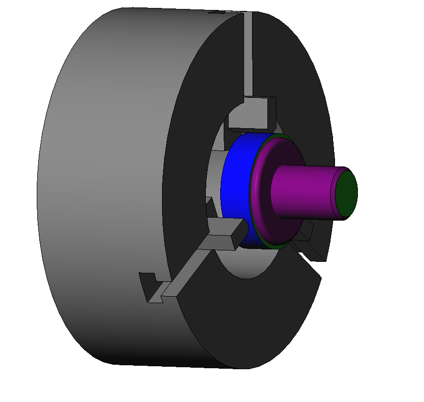
Now simulate.

Look to make sure there are no crashes.
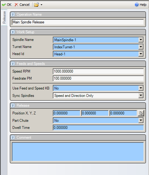
Now go back to your Solidturn toolbar and click release.

Enter the following information into the dialog box.
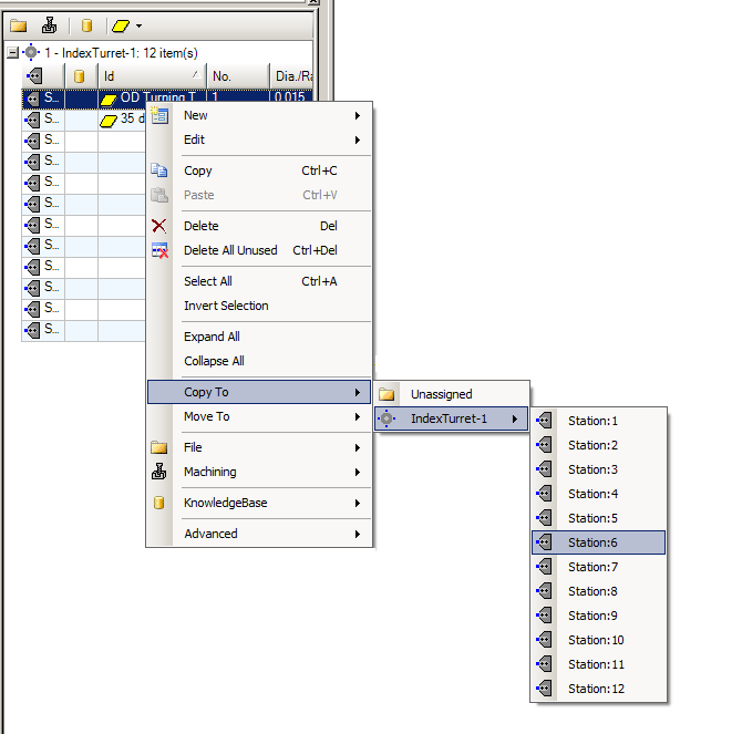
Now we need a reverse tool to do the back side.
Go to your tool tab. Right click your OD tool.
Now open the copied tool.

Enter the following information.


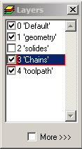
Open Layers and select the chain layer.
Select the geometry on the back of the part.
And click Autochain.
Name the chain Back Face
Hide the Chains Layer
Select the geometry on the shoulder of the part.

Click Autochain.
Reverse direction of chain by selecting reverse direction.

Unhide chain layer.
Rename the new chain Back Turn OD.
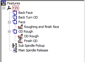
Select the Back Face chain and click Roughing on the Solid Turn Toolbar.
Related Content
For more tutorials see CADCAM
More Esprit CAM Tutorials
Esprit CAM Tutorial-Creating & Adding Tools
Esprit Lathe Tutorial-Drawing 2D Geometry
Esprit CAM Tutorial- Creating & Setting Up Lathe Stock
ESPRIT Mill Tutorial- B Axis Setup
Esprit CAM Tutorial: Lathe Sub-Spindle Setup
Esprit CAM Tutorial: Lathe Basics
Esprit CAM Tutorial: Introduction To Esprit CAD/CAM
Esprit CAM Tutorial: Orientating Part Model For Lathe Operations
Esprit CAM Tutorial: Setting Mill Up Stock
Esprit CAM Tutorial: Creating Layers
Esprit CAM Tutorial: Orient Mill Parts