CAD/CAM Tutorials


CAD/CAM Help & Consultation
-
 Fusion 360 CAM Help$20.00
Introduction To CAD/CAM
2D Geometry AKA Wire Frame:
DXF Files
DWG Files
Geometry (Wireframe or 2D Geometry)
Entity(Elements)
Lines
Circles
Points
Rectangles
Arcs
Geometry Reference Tools
Workplane (Construction Plane)
Snap Points
Endpoints
Center Points
Reference Lines
Each individual segment is called an entity or an element.
A series of entities forming a rectangle is also considered an entity
3D Tools
Extrude
Revolve
Radius
Chamfers
Feature: a distinctive aspect of the geometry, shape or form of a component.
Ex: A hole pattern, pocket, face, thread and etc.
Toolpath: The path that a tool moves about in the machining process.
Axis:a real or imaginary line on which something rotates, or a straight line around which things are evenly arranged. An example of an axis is an imaginary line running through the earth on which the earth rotates.
Concentricity/ Concentric:
What is the part used for? (Application & functionality)
What are the critical dimensions and features?
Making Parts:
- What are you making? (size, dimensions, tolerances)
- What stock material are you using? (size + material = grade)
- What machine are you going to make it on?
- What tools will be used to remove material
- Manufacturing process (order of operations/ workholding).
Getting Started With Fusion 360
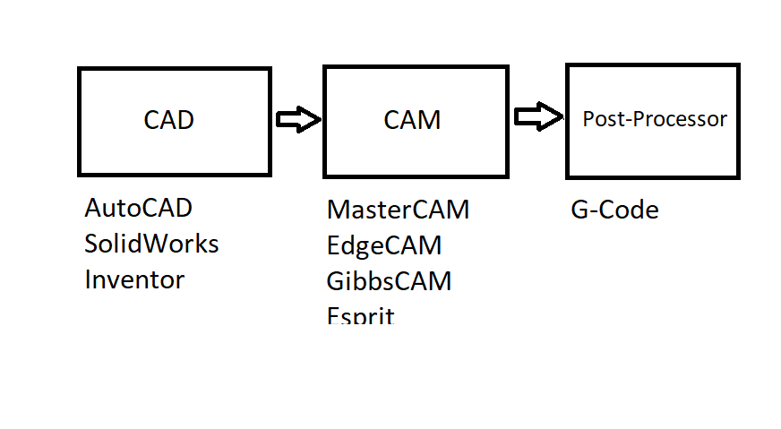
What is CAD/CAM?
What is Fusion 360 and What Are The Applications?
- CAD
- Designing
- Engineering
- CAM or CNC programming software
Who uses Fusion 360?
- Designers
- Engineers
- Machinist
- Makers
Fusion 360 Workspace
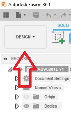
Getting Started With Design Mode
- Create sketches
- Select construction plane
- Mouse Functions
- Toolbar Layout
- Workflow
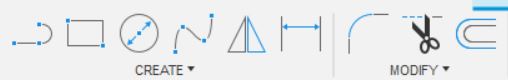
2D Sketch Tools
- Line
- Rectangle
- Circle
- Spline
- Mirror
- Dimension
- Radius
- Trim
- Offset
Sketch Dimensions & Constraints
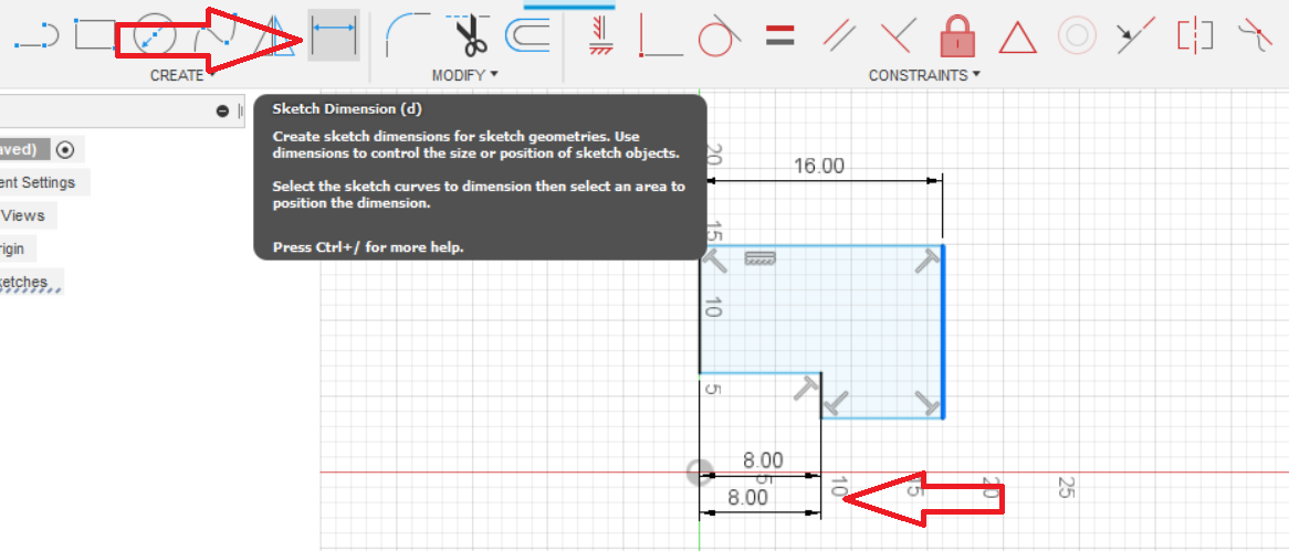
- Use the “Tab” keyboard key to switch from vertical dimension input to horizontal input.
- To edit or a dimension; double click the dimension and type new distance.
Snap Points: A geometry point on a 2d sketch that’s used as a positioning tool position geometry in specific locations.
- Endpoints
- Midpoints
- Center Points
CAD/CAM Dictionary
4th Axis – 4th axis is a term used to describe a machining process or toolpath that moves along the XY and Z-axis but usually revolving around the X-axis on a mill.
Axial Tools – Machine tools parallel with the workpiece.
Axis – A spatial direction along the path of motion. There are three primary axes, X, Y and Z. Each primary axis has a relative axis along that axis; A, B and C.
A-Axis – The axis of motion that revolves along the X-Axis.
B-Axis – The axis of motion that revolves along the Y-Axis.
C-Axis – The axis of motion that revolves along the Z-Axis.
Chip Load – Chip load is the amount of material removed by each flute of the cutter.
Boolean – a 3d modeling function used to modify or create a solid body by combining, subtracting, or intersecting more than one body.
Boundary – a geometric parameter of constraint used to confine or exclude a toolpath.
B-Rep – Boundary Representation ( B-Rep) : a method used in solid modeling to define geometry that’s represented by edges, faces, and vertices.
CAD – Computer Aided Design; The use of computers to assist in the design process.
CAM – Computer Aided Manufacturing; The use of computers to assist in manufacturing.
CAD/CAM – Computer Aided Design and Computer Aided Manufacturing.
Cartesian Coordinates – A three dimensional system used to represent a position, location, or direction of motion in space.
Chip Evacuation – Chip evacuation is a process of removing shavings or material removed from a feature of a part being machined.
Chip Load – Chip Load is the amount of material removed by each flute of the cutter.
Circular Interpolation – A toolpath that moves along a circular arc. Circular interpolation is defined by: an endpoint
- an endpoint
- a feed rate
- a center point or arc center
- a radius
- a direction of movement
Chamfer – an angle on the two intersecting edges of a part.
Closed Profile – a chain of geometry that connects together without any gaps.
EX.
0 an “o” shaper is closed, or a closed profile.
U a “u” is an example of an open profile.
Collision Detection – A CAD/CAM software feature that detects or predicts a collision of the tool and the part or stock being machined.
Concentricity / Concentric – Two round circles or round surfaces that share the same centerline / axis of rotation.
Constraints – Spatial parameters or boundaries that are used to define relationships within geometry. Constraints may be used to associate parametric or variationally geometry within a CAD system.
CSG – Constructive Solids Geometry (CSG): a 3d modeling method using primitives to build more complex models and Boolean operations of add, subtract, and intersection.
CDC – Cutter Diameter Compensation (CDC) : A programming method used to alter a toolpath to compensate tool diameter wear.
Cutter Offset – The axial distance from the cutting tool center to the cutting tool diameter (Tool Radius).
Cycle – The sequence of operations and repeated processes that a CNC executes within a program. also see Cycle Time.
Depth of Cut or DOC is the depth of cut of the end mill into the part surface axially. With CNC milling, it is measured in the Z axis direction.
Dimensional Error – errors in part dimensions and size after the CNC g code program has run a part or setup piece.
Distance To Go – Distance-To-Go is a CNC machine tool that can be used to prevent any machine crashes when running a program for the first time. The tool displays the programmed distance the tool is to travel on that specific line of code. After the CNC program is proven out or proven to work Distance To Go is no longer needed to be used.
Double Geometry – Double geometry is a geometry that overlaps over other geometry in the same position. Example:. line segment overlapping another line segment. Two lines but appears as one line.
DWG – A 2d CAD drawing file format commonly used in Autocad.
DXF – DXF (Drawing Exchange Format): a common file format for 2d CAD drawings and geometry used to transfer CAD data from one CAD system to another.
Gap – Gap or profile gap is a gap in a profile where the geometry chain doesn’t connect.
Interpolation – A CNC function generates data points to control movement to a given coordinate position.
Lathe Driven Tools – independent driven tools / mill tools.
Key – A part that is designed to be a sheer point or point of failure to prevent important mechanical components from being damaged in an event of mechanical bind.