“Repetition is the mother of all skill”
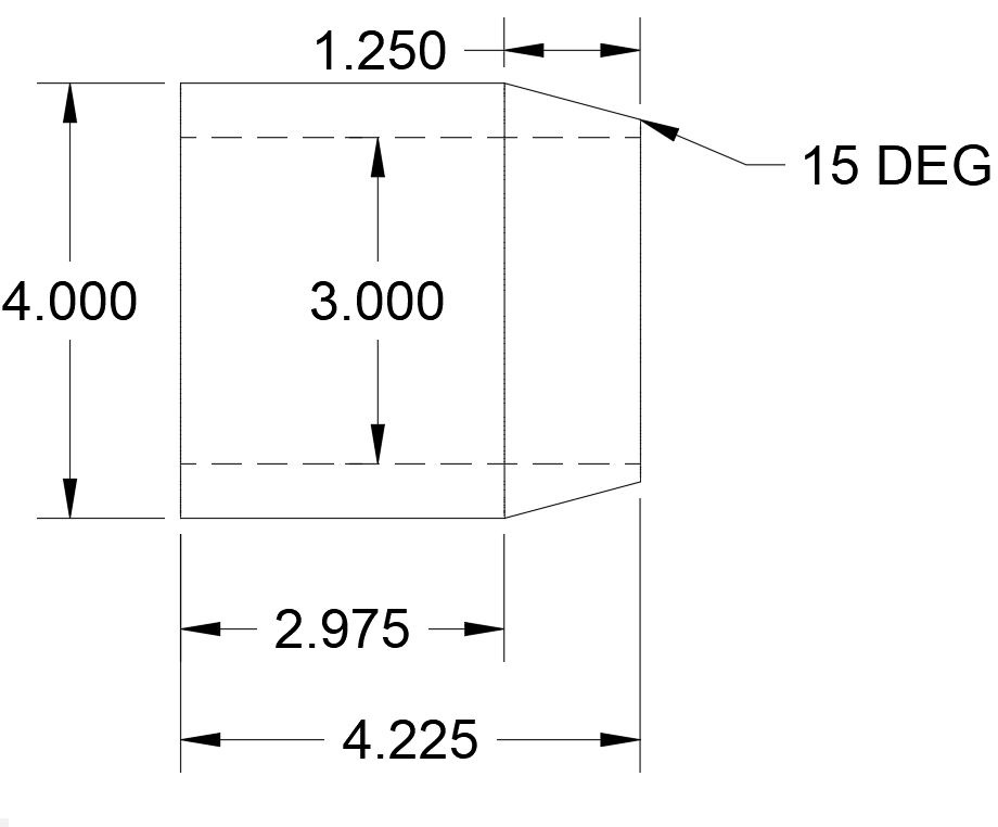
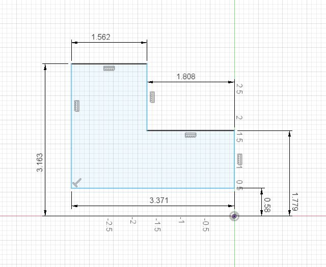
Lathe Parts: Spun Profiles & Center of Rotation – Round parts with diameter dimensions must be defined by the cross section or lathe contour of the part. The diameter dimensions must be divided by two, to define the radius values because you’re only drawing the cross sectional view of a spinning profile along the center of rotation. Note: The generated g-code is usually diameter values.

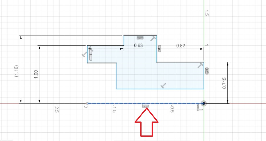
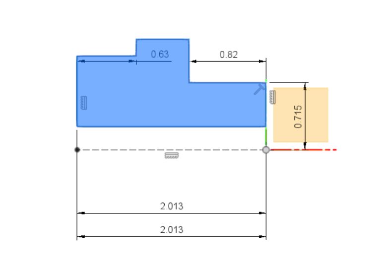
Start off by drawing the cross section or lathe contour of the part without chamfers.
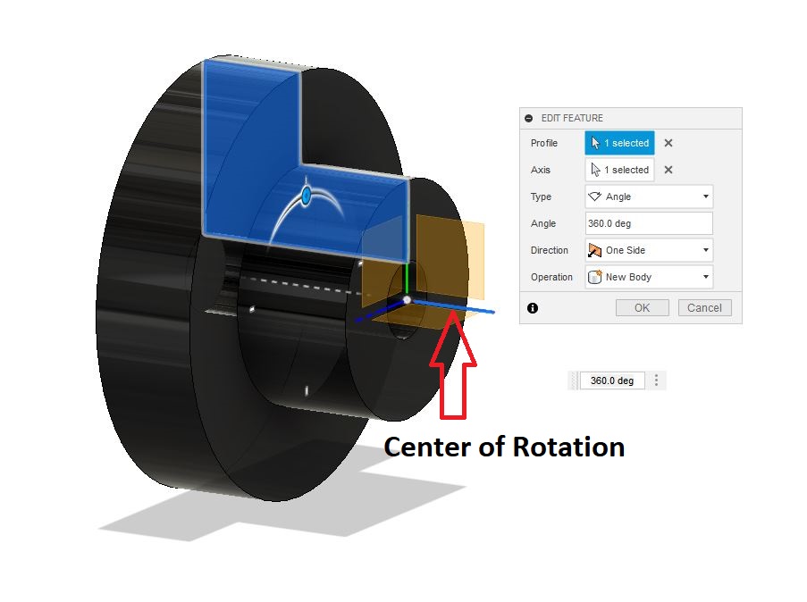
Revolve Tool: Revolves a selected profile around a selected axis. See More Terms
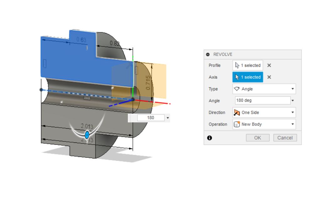
Lathe parts need to be revolved 360 degrees.
Axis: A spatial direction along which the path of motion. There are three primary axes, X, Y and Z. Each primary axis has a relative axis along that axis; A, B and C. Revolve Tool: Revolves a selected profile around a selected axis. See More Terms
Draw The Three Cylindrical Bodies (round lathe parts).
Each part should be saved as its own separate file. Use the names below for each file saved.
- Lathe 1_A
- Lathe 1_B
- Lathe 1_C
Part # Lathe 1_A

Start off by drawing the cross section or lathe profile of the part without chamfers. All 45 degree chamfers will be added after the general shape of the part is defined.

The lathe contour must be “revolved” around the center of rotation(axis).
Chamfers
Most chamfers are 45 degrees unless otherwise specified. Only 45 degree chamfers can be created with the 2d or 3d chamfer tools. Any other angle than 45 degrees will have to be drawn with the “Line” and “Dimension” tools.
After the lathe contour is revolved into a solid model; add the chamfers.

Part # Lathe 1_B

Part # Lathe 1_C