CAD Drawing
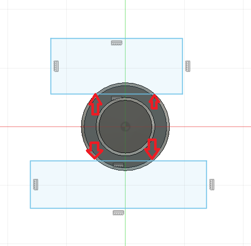
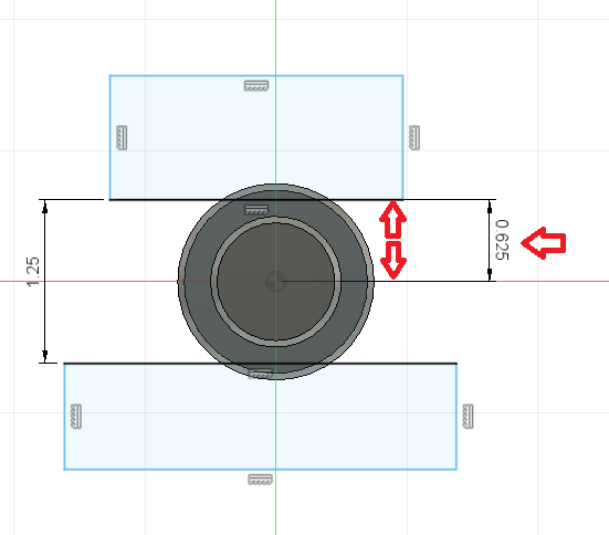
- Draw the main circular body of the part without the flats.
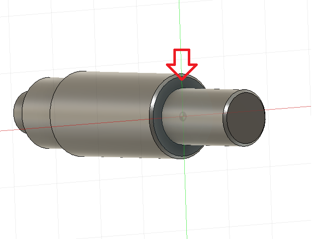
- Create a new sketch plane of the face of the ⅕” Diameter Body.
- Draw two rectangles any size that cross over the 1.5” OD Circle. See red arrows below
- Dimension the vertical distance of the two rectangles to be 1-¼ or 1.25” apart.
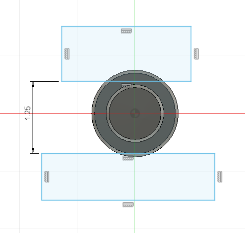
- Dimension the bottom line segment of the top rectangle distance to be 1.25”/2 or .625” to the center origin.
A usable CNC program or CAM file is created around the process of getting from “Point A” to “Point B.”
Point A is the current stock size and material.
Point B is the finished dimensions and print specs.
To get from “Point A” to “Point B” the machining processes have to be properly planned.
What machines will be used?
What cutting tools will be used?
How will you hold the part in order to remove the material?
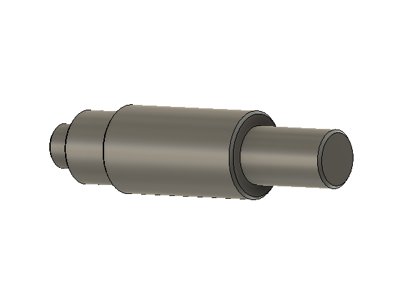
Stock Size 1.5″ x 6″ Long
Machine Operations
- Lathe OP1
- Lathe OP2 (Flip part over in machine(make new setup in Fusion 360 and have Z+ facing the opposite direction of Z+ on OP1.
- Mill OP (flats)