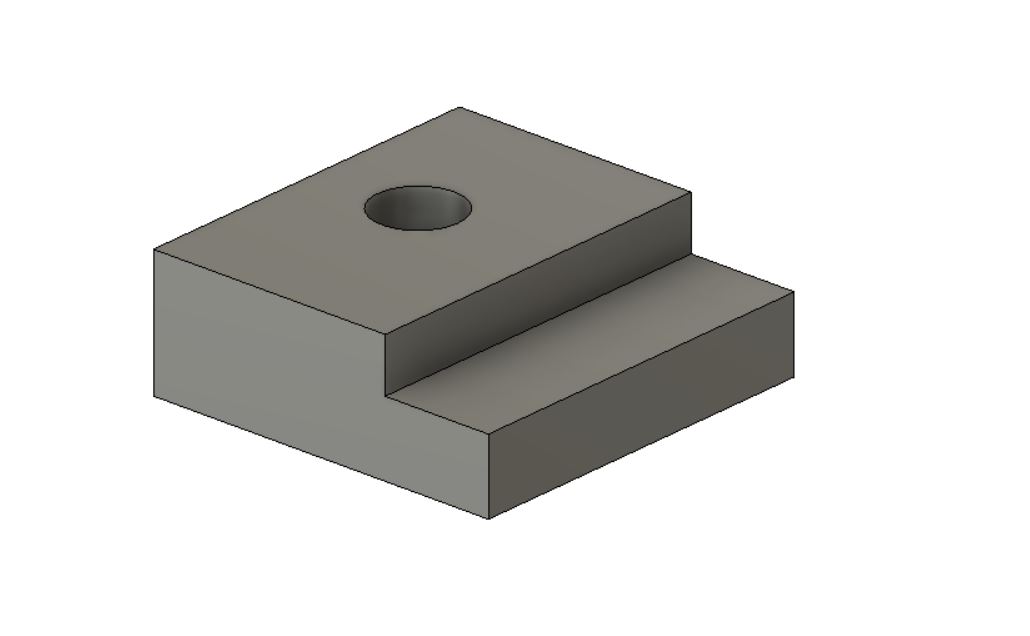
A CAD/CAM toolpath is the CNC’s programmed path the tool takes in order to remove metal from a workpiece.
There are different types of toolpaths that a CNC takes in order to produce a finished part. Some toolpaths feed into the material at a programmed feedrate and speed as the cutting tool removes material. Other toolpaths are used to position the tool as the machine travels to enter the workpiece and exit the workpiece.
Types of toolpaths:
- Feed (Cutting) toolpath
- Rapid toolpath
Rapid traverse movements are used to reduce cycle time as the machine positions itself in the programmed location to begin the next cutting pass or series of cutting passes.
Concepts To Know:
- Tool Positioning
- Lead-In (Entering the Material)
- Lead-Out (Exiting the Material
- Lead-In / Lead-Out toolpath
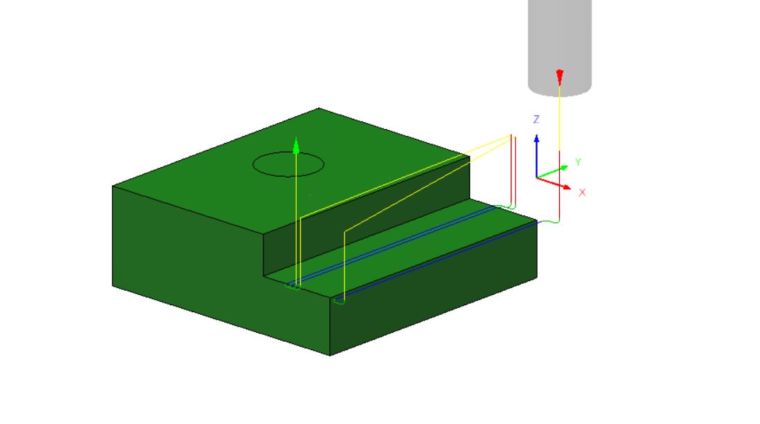
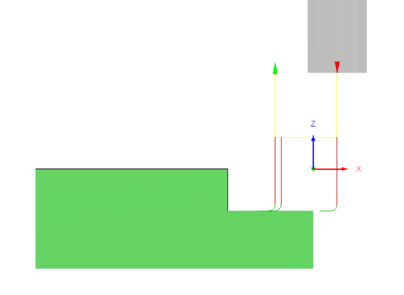
Toolpath Color Scheme
CAM software illustrates the generated toolpaths using different colors so the user can distinguish the cutting process in the CAM simulation. As the programmer generates the needed toolpaths to produce the part the toolpath color and structure can be used to verify the correct processes and parameters are being used. This will help minimize any “machine crashes.”
- Feed (Cutting) Toolpaths Blue
- Rapid Traverse Toolpaths Yellow
- Lead-In / Lead-Out Toolpaths Green
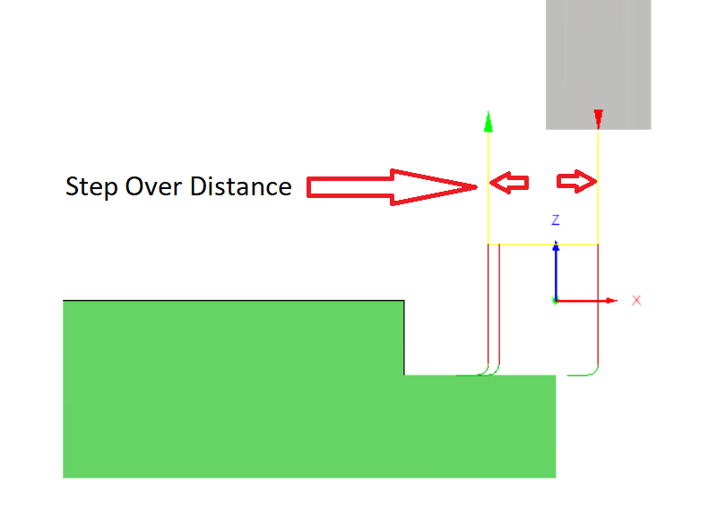
Cutting Passes & Tool Step Over
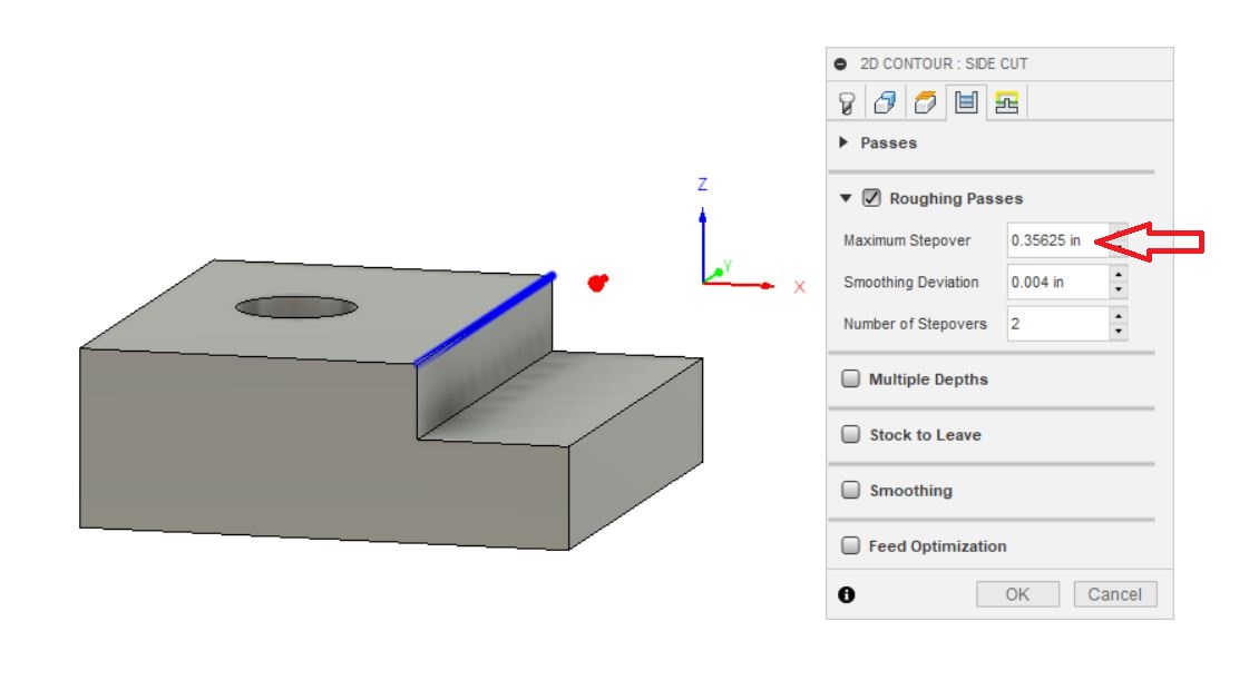
Outside Parameter: Cutting all sides and Squaring Up The Part
Outside Parameter: Cutting all sides and Squaring Up The Part
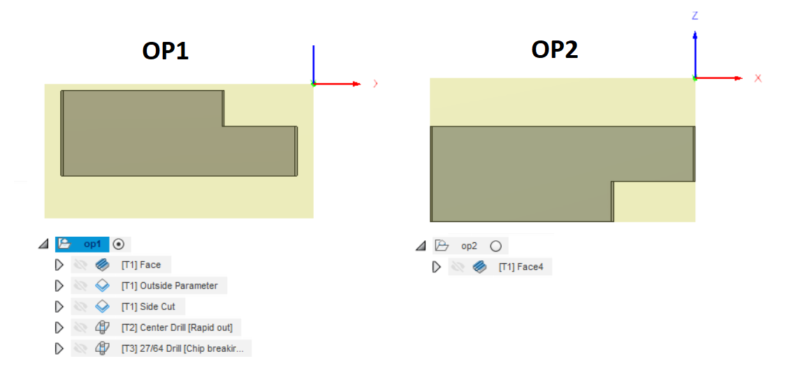
Use 2d contour
