Although this page will be used to document and collect resources to implement a toolchanger on the SolidCore printer, we’ve only completed one so far for this case study. The following design analysis is discussing a toolchanger project we prototyped for our customer, Nandan. The majority of the topic currently being discussed is of the work of our customer, Nandan. The design and prototype uses parts designed by Nandan, 3D Distributed, and Nandan’s application of E3D’s open-source toolchanger design – SolidCore CoreXY parts.
ToolChanger Project
Nandan designed a toolchanger setup based on the SolidCore Belt System and E3D Toolchanger geometry. Although the project took longer than expected to complete, it was an adventure in design and manufacturing options that brought much insight to future design possibilities. CNC machining operations and workholding techniques can limit design. The manufacturing process has to be thought out and planned. Some of the parts designed and used I would’ve never thought of myself without Nandan. The design uses MGN9 linear rails on the y-axis and an interesting variety of E3D and SolidCore mods.
- See Solidcore Printer
- See E3D Toolchanger
Parts List – Designed by Nandan To Be Machined
1) QTY 4 of Belt Clip.dwg
2) QTY 2 of IdlerPlate.dwg
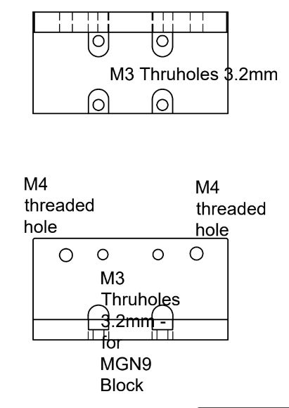
3) QTY 2 of MGN9_Block.dwg
4) QTY 2 of MotorPlate.dwg
5) QTY 2 of X-BeltPlate.dwg
6) QTY 1 of X-Block.dwg
7) QTY 1 of Y-Carriage_Left.dwg
8) QTY 1 of Y-Carriage_Right.dwg
Machined Components
- 2 x motor mount plates
- 2 x idler mount plates
- # x a variety of modified or similar to SolidCore parts and E3D toolchanger designs.
X-Carriage
The X-carriage assembly is staged on a MGN12H block with MGN9 rail on the y-axis. The x-carriage assembly clamps to a MGN9R rail rather than the MGN12-H used on the common SolidCore build. The E3D Toolchanger system is adapted in order to switch heads.
Y-Carriage
The carriage design uses belt clamps to mount the gt2 belt down and two plates that mount together using an aluminum block fixed to a MGN9 linear rail carriage block.
A custom y-axis carriage similar to SolidCore’s Y-carriage is mounted to the MGN9H Block similar to what you already have but with a little twist. The carriage width and hole pattern need to line up with the E3D toolchanger plate hole pattern. The Face Plate and Rear Plate are separated by 28mm with 4 screw holes at 30mm x 43mm.
See E3D pdf links below
Parts used are similar to the following E3D Print Dimensions:
1 x MS-X-Block
2 x MS-X-Belt Plate
Design Constraints & Considerations
The attached PDF of the belt plate of the whole carriage would be needed. A larger belt plate with 3 specific holes is needed to attach a spring loaded connector milli max 868-10-004-00-012000 to get a single part fan power to tool heads and then move the belt hole further to the left.
Some parts could possibly be machined as a single piece, kind of like the current design. There is a little mod though I need to use what E3D has.
Specific measurements of the placement of the 3 holes can be provided. All the belt holes would need to line up with the X carriage assembly on standard SolidCore.
E3D X-Belt Plate
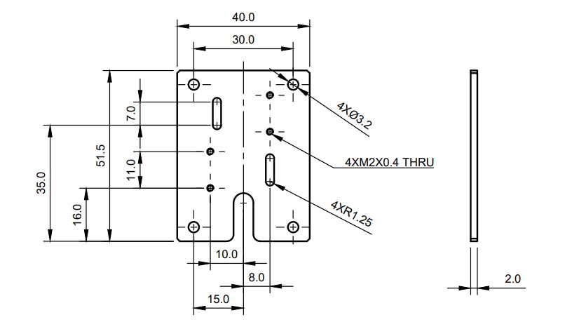
Designing A Carriage Including X-Belt Plate Hole Pattern
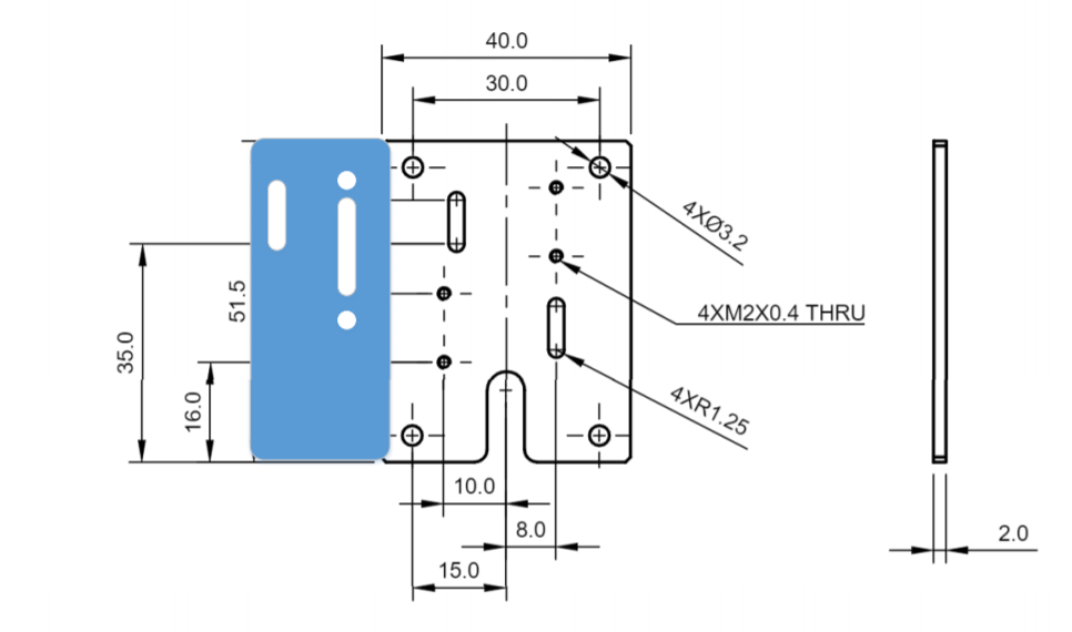
Custom Y-Carriage Design w/ X-Belt Hole Pattern

Reference E3d PDF
1 x https://github.com/e3donline/Motion-System/blob/master/PDFs/MS-X-BLOCK%20v1.3.pdf
2 x https://github.com/e3donline/Motion-System/blob/master/PDFs/MS-X-BELT-PLATE%20v1.6.pdf
1 x Bowden style hotend mount
3 x z-axis bed drive mounts
3 x z-axis motor mounts
3 x z-axis lead screw idler arm
X Carriage Pulley Layout
The X carriage and MGN rail clamp needs to move the pulleys closer to line up with the y-carriage, which is 10mm shorter than standard SolidCore layout.
X-Carriage Pulley Layout Explained
The reason the pulleys on the standard SolidCore x-carriage are so far apart is to line up with the y-carriage. That’s why c-channel stock is used. We have future plans to change this in the near future to be made from solid bar in order to get those pulleys closer which would increase travel and allow a belt tensioning mechanism to be used. Adapting the design to support both mgn12 and mgn9 blocks, in order to get the E3d Tool Changer head with the parts available by E3D.
Y-carriage to be machined:
Changing the depth of the MGN rail clamp to attain the correct height. A spacer between the rail and the x-carriage may need to be used but if a custom y-carriage is needed it is easier to change the position of the belt slots.
Note: Pulleys, idlers, and spacers, etc used need clearance.
Belt Clamps


Updated
1) X-Carriage – The X-Carriage will be modified to support 9mm Gates GT2 pulleys and belts, which may stretch less and are better than 6mm belts. Consideration: U-Channel #9001K976 from McMaster Carr will work with 9mm belts.
2) Y-Carriage – U-channel isn’t available (in North America) that works with an MGN9H block (to add rigidity, an option is to attach the MGN9 rail to a Misumi Series 3 15mmx15mm extrusion). If so, the E3D toolchanger changer pieces purchase of the shelf.
Machine MS-X-BLOCK from E3D’s attached step file as is, or 5/16″ thick blank can be cut, drilled and tapped. However, for the belt plate it really needs to be a 2mm thick aluminum plate which would need holes drilled. Nandan will redesign the plate (seen in the MS-X-BELT-PLATE pdf) to support setup of the 9mm belt.
Options – mod the idler mount plates to add a tensioner mechanism.
Needed:
- X and Y carriages with rail clip
- Motor and Idler plates
Design Constraint – Available Stock Material Sizes
Rather than ordering the u-shaped stock, it can be made from solid bar stock. Sourcing the 2mm aluminum plate will be difficult so it might be easier to use 1/8″ and cut it down. Nandan has a toolchanger wired to the duet wifi in a specific way that allows for replacing tools and hotend easily.
Update – Returned to the 6mm belt. 9mm will have to wait.
Nadan’s Autocad Files Overview
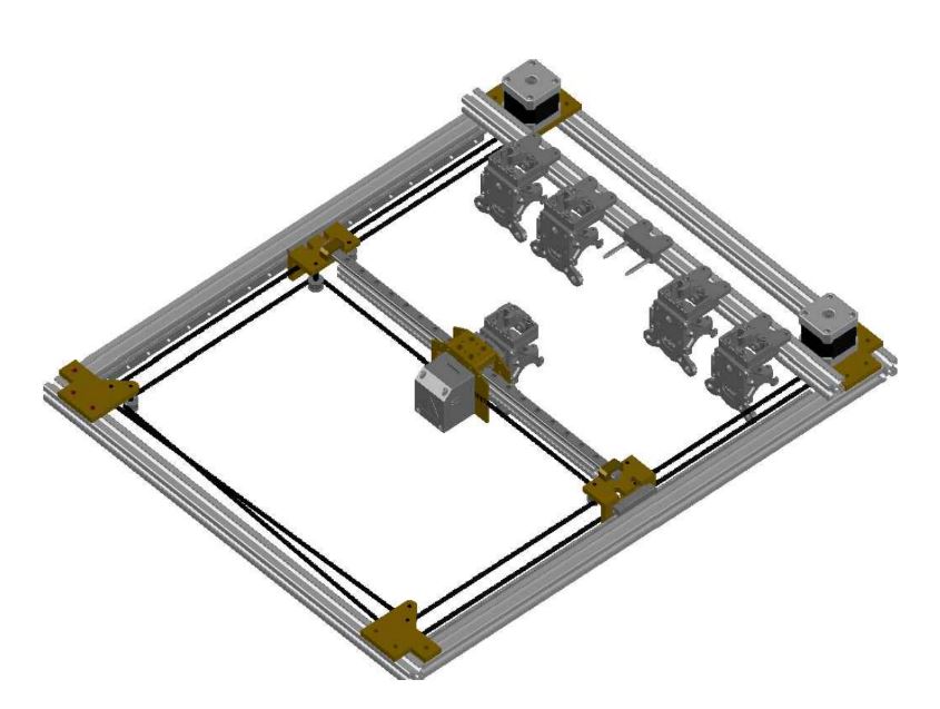
a) In drawing 1 the frame is based on the Solidcore design with the MGN9H rail mounted on top. This was done in order to mount a 2020 extrusion with the E3D toolhead mount bracket, so as to line up with E3d’s docking system and already machined parts.
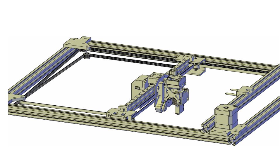
b) In drawing 2. I have removed the toolhead so you can see everything else, the main thing here is you can see the modified Y-axis carriage.
Waiting On Parts Check all the dimensions of what needs to be machined makes sense. It looks good in CAD based on theoretical measurements.
Dwg – parts needed:
1) QTY 4 of Belt Clip.dwg
2) QTY 2 of IdlerPlate.dwg
3) QTY 2 of MGN9_Block.dwg
4) QTY 2 of MotorPlate.dwg
5) QTY 2 of XBeltPlate.dwg
6) QTY 1 of XBlock.dwg
7) QTY 1 of YCarriage_Left.dwg
8) QTY 1 of YCarriage_Right.dwg
SolidCore Parts
- XY Motor Plates
- XY Idler Plates
- Belt System Components
XY Motor Plates
Motor Plates: The motor plates are the standard SolidCore plates.
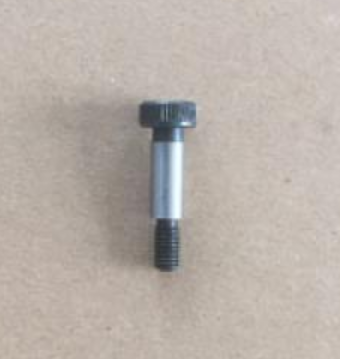
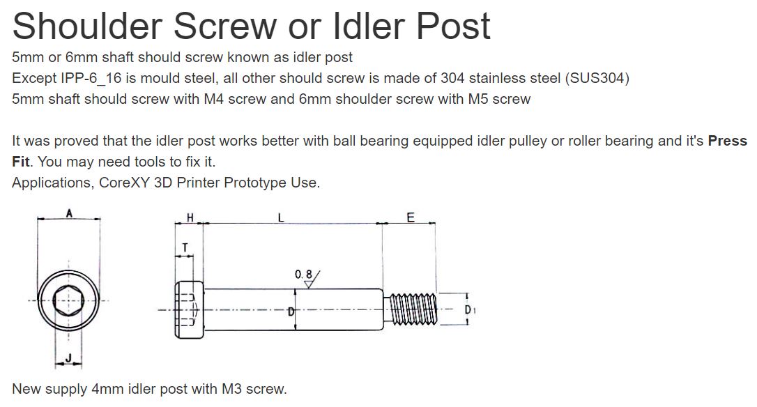
The standard SolidCore XY-Idler and motor plates will be used as before. However the X Carriage is to be changed due to design compromises if the available U-Channel stock material is to be used. The belt system will use shoulder bolts rather than the M5 Cap Screws that is currently being used on the SolidCore X-Carriage and XY Idler Plates.
Motor & Idler Plates
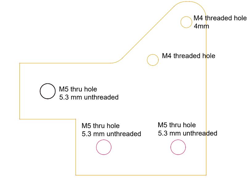
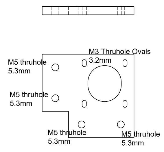
The Idler Plates will now use M4 Threaded holes to attach to the Shoulder Screw Idler Post.
Nandan changed the Y Carriage U brackets to be 1/4″ L brackets machine the same as you had. Also the left side and right side carriage brackets are different due to slight idler offsets.
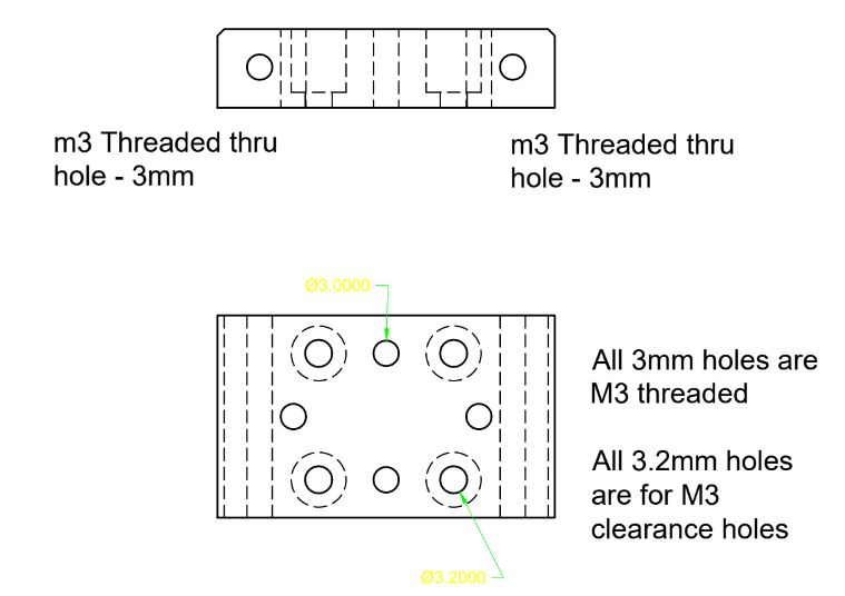
The pdf’s explain what holes need to be tapped (threaded) and which are to be thru holes for screws (unthreaded). All the dwg files are in metric mm units.
X-Carriage Bracket Assembly
Parts List – X-Carriage Assembly
X Carriage brackets with 2 MGN9H mounts = 2pcs
The X-axis Carriages are asymmetric
A MGN9 Rail mounts on for proper height to mate with toolchanger assembly.
The E3d smooth and toothed idlers have a different diameter and need to be offset slightly due to the belt width. In addition the Gates pulleys use a different screw hole for the idler posts.
Nandan’s design uses a L-bracket (U-channel with the bottom part of the U cutoff) rather than c-shape or u shaped aluminum on the SolidCore, not to limit the design options to the U-Channel used by the SoldCore carriage and can be an L-bracket (U-channel with the bottom part of the U cutoff). doesn’t want the carriage design to be limited to the U-Channel SoldCore carriage.
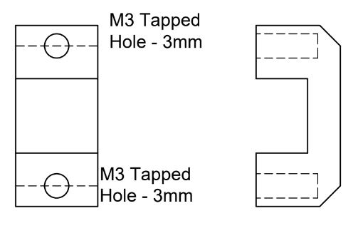
1 X-Block, 2 Belt plates, 4 Belt clamps: The Y-axis carriage has to be fully custom machined. Nandan designed the parts using the E3d design with some modifications to the E3d design to assemble to 2020 extrusions. The custom block mounts to the linear rail 4mm taller than the E3d part. 4 Belt clamps that are the e3d design that need to be machined. And the custom belt plate that needs to be machined and also be 2mm thick, of which I need 2 copies of it, this needs to attach to the custom block and also be able to accept e3d toolhead.
X-Carriage Drawing
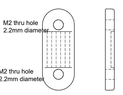
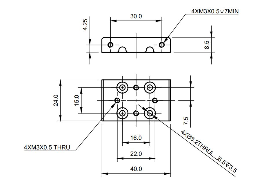
MGN Linear Rail Clamps