
Keyways & Keyseats
Key and Keyway Applications
- Pulleys
- Sprockets
- Other rotating assemblies that transfer motion
Purpose of Keys and Keyways
- A designed sheer point or point of failure to prevent important mechanical components from being damaged in an event of mechanical bind
- To make a component or set of components easier to assemble or more interchangeable
Video
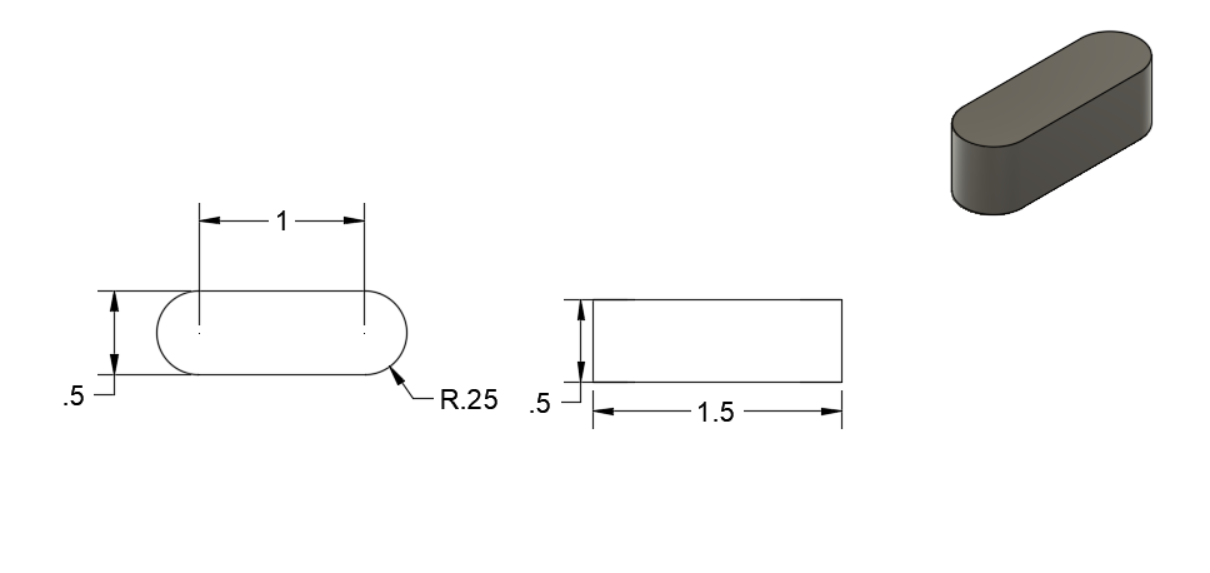
Draw the following parts:
- Key
- Keyway Bushing
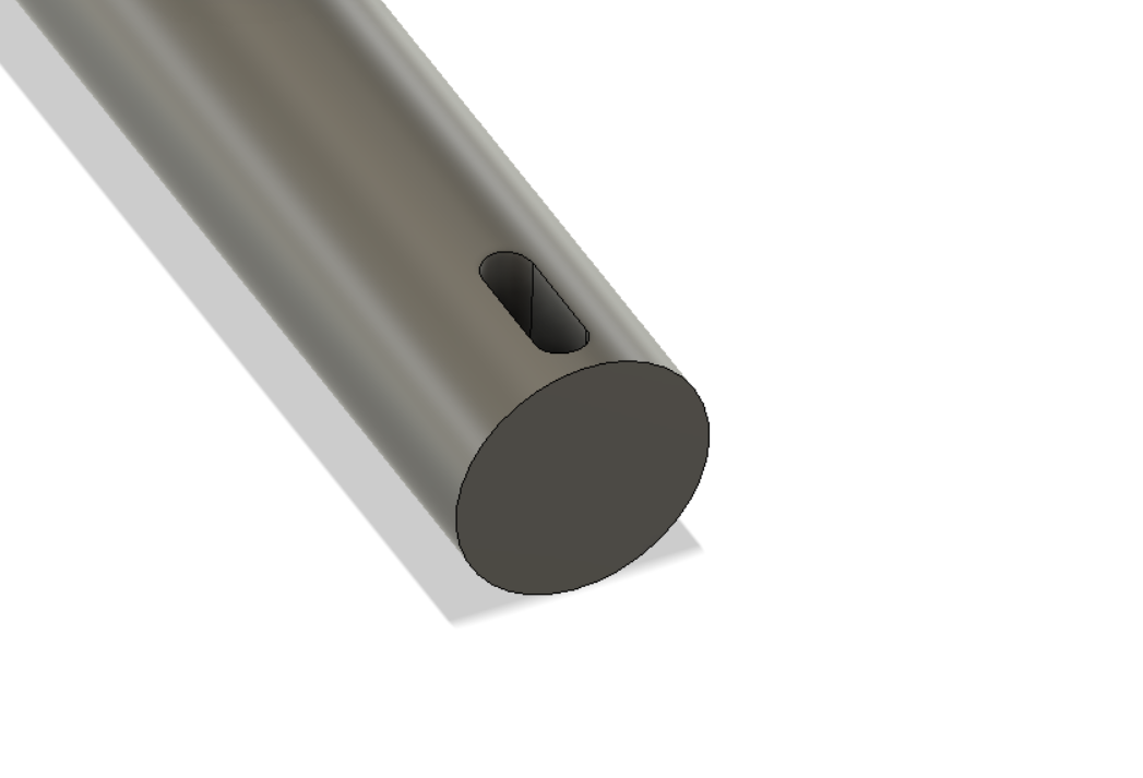
- Shaft with Keyseat

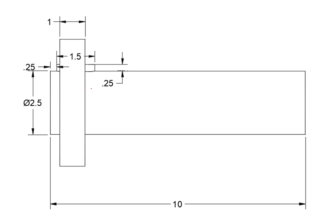
Drawing The Keyseat Shaft
There are two ways of drawing the keyseat in the shaft:
- Draw the keyseat from the center of the part and extrude cut. Then use the extrude tool to modify keyseat depth.
Drawing the keyseat from the center of the shaft example
Sketch plane is in the middle of the shaft.
Shaft OD = 2.5”
Key =.5”
*Note* ½” key should seat .25 deep into keyseat
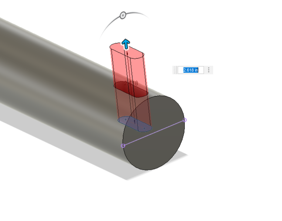
The keyway depth goes to the center of the part.
If:
Shaft OD = 2.5”
Key =.5”
*Note* ½” key should seat .25 deep into keyseat
And keyway is down to the center of the part = 1.25” Deep
2.5” / 2 = 1.25
if key should seat .25 deep into keyseat
1.25” – .25” = 1.0”
Extrude Key face up 1”
Extrude Key face up 1”

A better way to draw the keyway is:
Extrude Key face up 1”
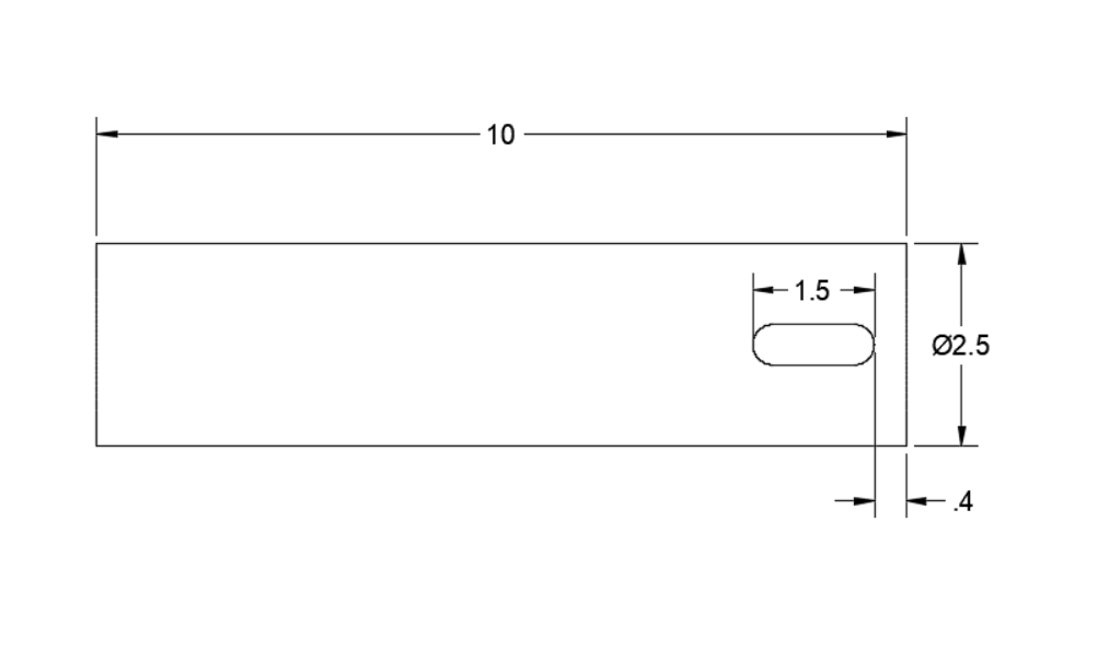
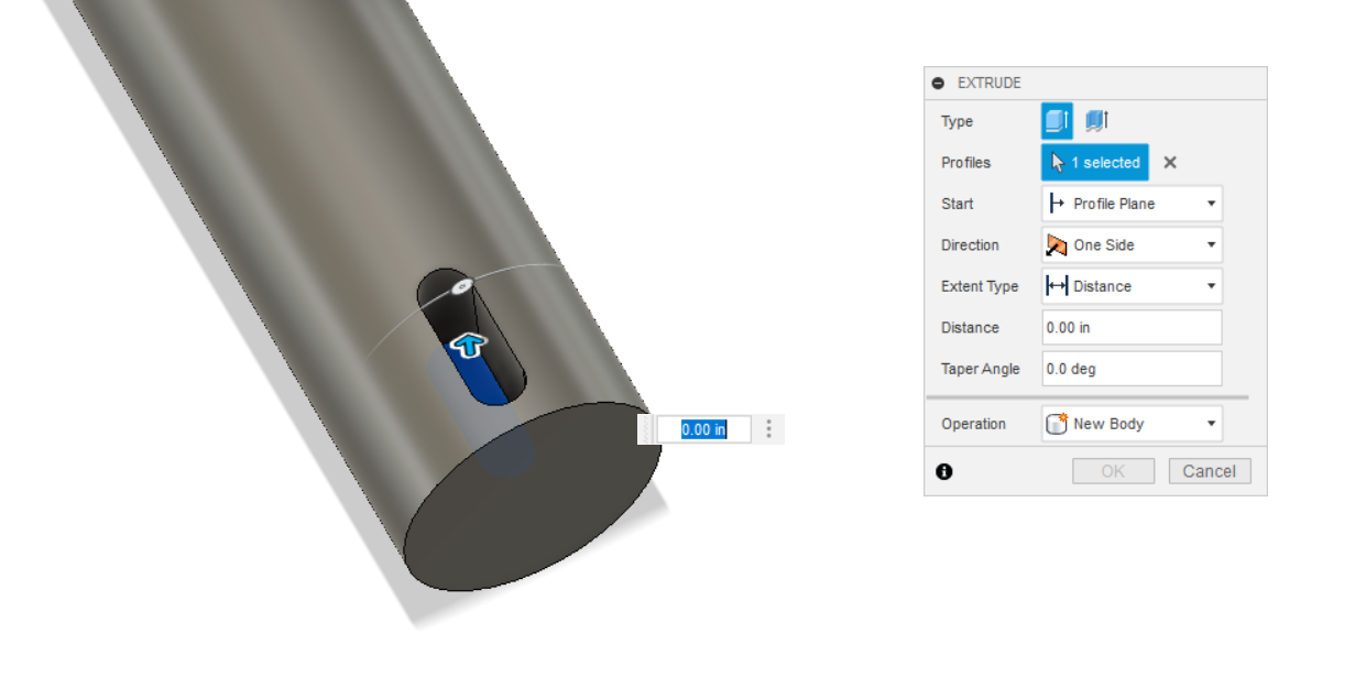
Drawing A Keyway Slot Using Offset Plane
A better way to draw the keyway is:
Use offset plane


Select a reference plane to offset from


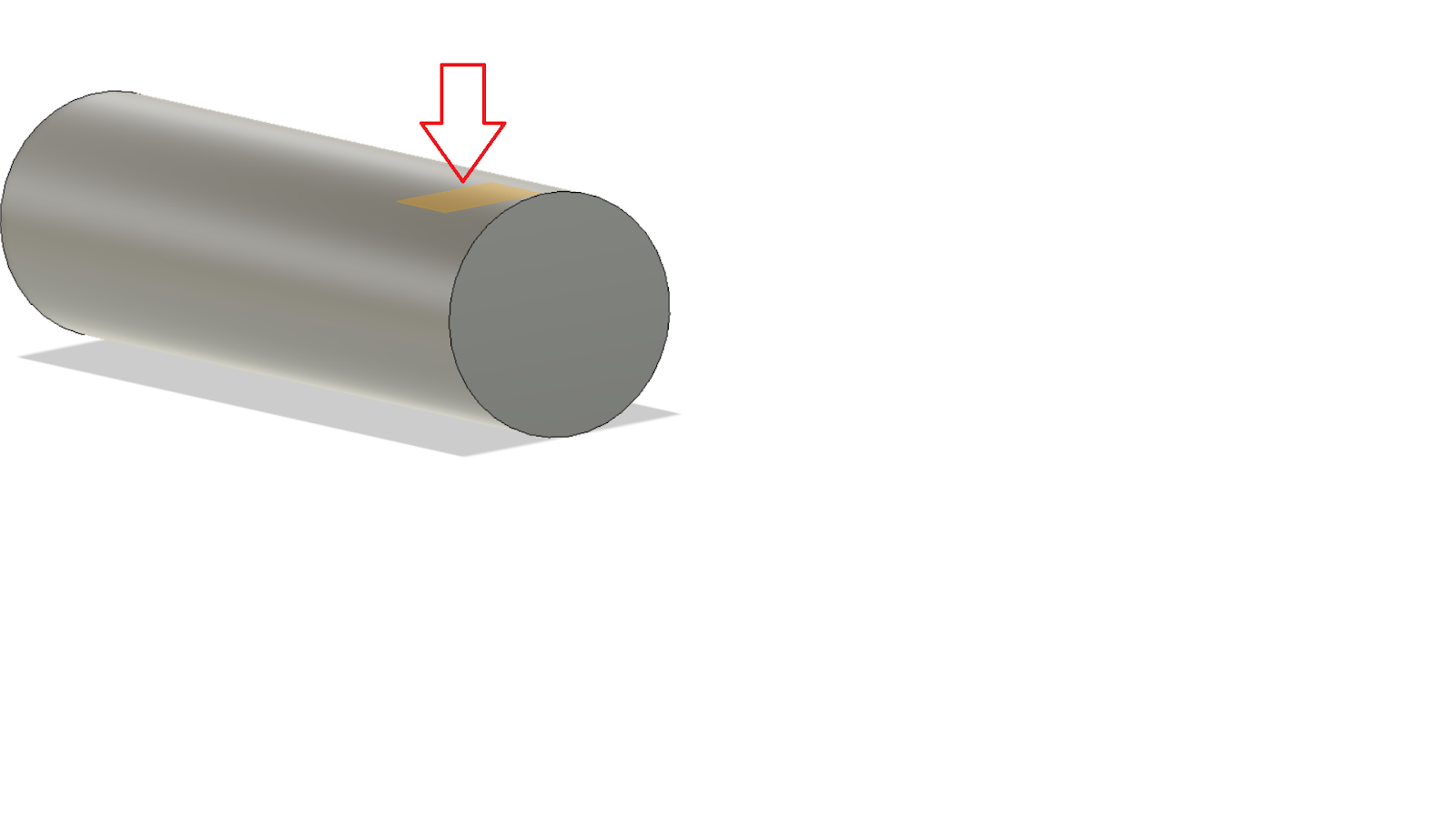
Select a new plane to sketch on.

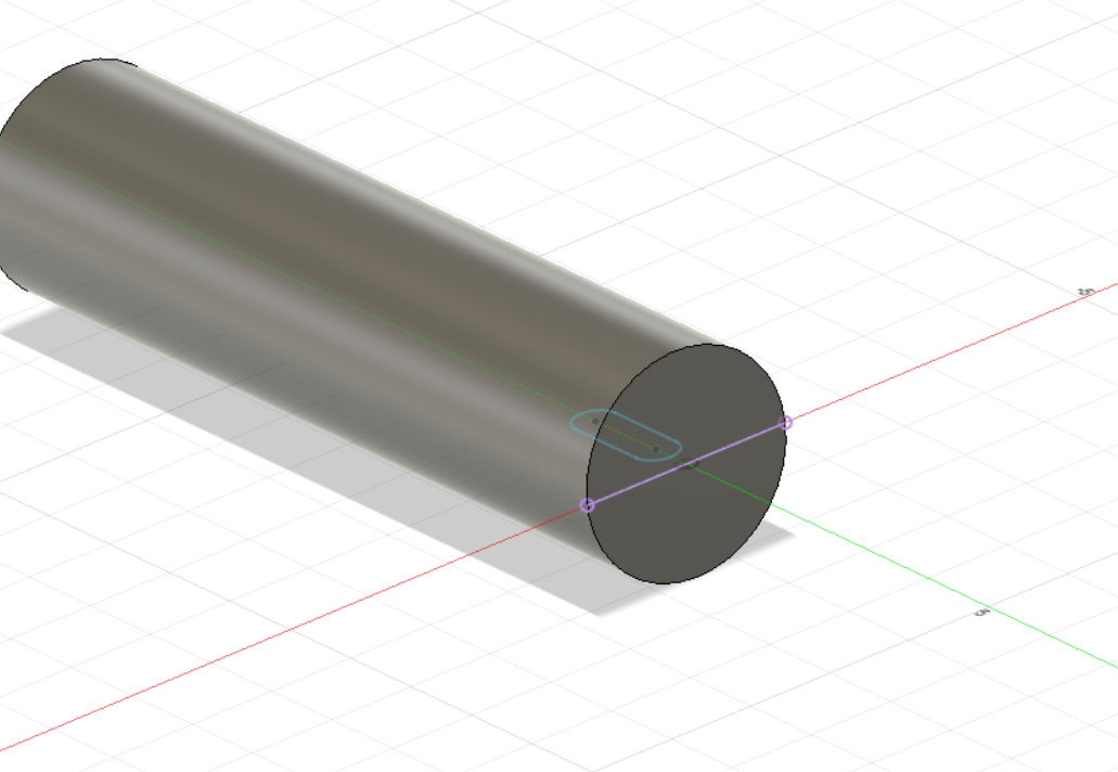
The sketch plane is now on top of the part. Draw the slot profile and extrude/cut to -.25” from the face.
Video for Shaft Keyway CAM toolpaths
Milling The Key Radius

Choose an endmill that will have enough clearance.