What Size Stepper Motor Should You Use?
While the size of a stepper motor is just the footprint it’s the winding that determines torque. There are Nema 17’s with as much torque as a Nema 23. Most 3d printers use stepper motors to drive z-axis motion lead screws to raise or lower the bed or gantry. The lead screw serves as a gear reduction increasing torque.
1.8 Degrees vs 0.9 Degrees
While many of the newer corexy designs use 0.9 degree motors to maintain synchronization of the two motors while moving in X and Y directions. The 0.9 degrees steps are smaller which reduces the dead zone between steps. This helps reduce artifacts found in printed objects.
There are two common step angles: 0.9 and 1.8 degrees per full step, corresponding to 400 and 200 steps/revolution. Most 3D printers use 1.8 deg/step motors.
Step Angle:
- 0.9deg motors have slightly lower holding torque than similar 1.8deg motors from the same manufacturer
- However, to produce a given torque, the lag angle needed by a 0.9deg motor is slightly more than half the lag angle of a similar 1.8deg motor. Or to put it another way, at small lag angles a 0.9deg motor has nearly twice as much torque as a 1.8deg motor for the same lag angle.
- At a given rotation speed, a 0.9deg motor produces twice as much inductive back emf as a 1.8deg motor. So you generally need to use 24V power to achieve high speeds with 0.9deg motors.
- 0.9deg motors need step pulses to be delivered to the drivers at twice the rate of 1.8deg motors. If you use high microstepping then the speed could be limited by the rate at which the electronics can generate step pulses. The interpolation mode at 16x microstepping of the TMC2660 drivers on the Duet 2 WiFi/Ethernet can be used to overcome this issue. The drivers on Duet 2 Maestro and Duet 3 can interpolate at any microstepping setting.
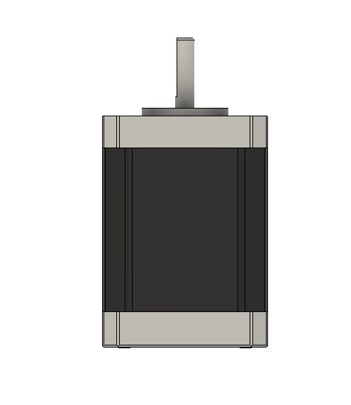
Nema Stepper Motor Dimensions
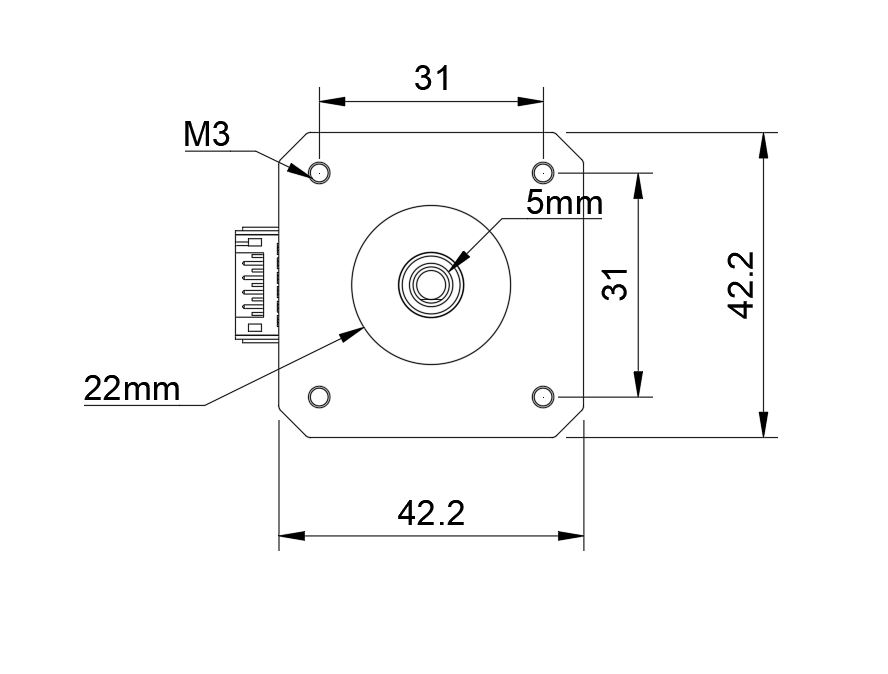
Nema Stepper Size
- Nema17 Size 1.7 inches x 1.7 inches
- Nema 23 Size 2.3 inches x 2.3 inches
- Nema 34 Size 3.4 inches x 3.4 inches
- Nema 42 Size 4.2 inches x 4.2 inches
Stepper Motor Holding Torque
Holding torque is the maximum torque that the motor can provide with both windings energized at full current before it starts jumping steps. The holding torque with one winding energized at the rated current is about 1/sqrt(2) times that. A motors torque is proportional to current (except at very low currents), so for example if you set the drivers to 85% of the motor rated current, then the maximum torque will be 85% * 0.707 = 60% of the specified holding torque.
Torque is produced when the rotor angle is different from the ideal angle that corresponds to the current in its windings. When a stepper motor is accelerating, it has to produce torque to overcome its own rotor inertia and the mass of the load it is driving. In order to produce this torque, the rotor angle must lag the ideal angle. In turn, the load will lag the position commanded by the firmware.
Micro stepping can reduce torque. This means that when the lag angle is equal to the angle corresponding to one micro step because you want the position to be accurate to within one micro step, higher micro stepping implies a smaller lag angle, hence lower torque. The torque per unit lag angle which is what really matters does not reduce with increased micro stepping.
Sending the motor a single 1/16 micro step results in exactly the same phase currents and therefore the same forces
Sending the motor 1/32 micro steps, or four 1/64 micro steps, and so on.
Unipolar vs Bipolar Stepper Motors
Bipolar Stepper Motor
- 4 wires
- 6 wires
- 8 wires
Unipolar Stepper Motors
- 5 wires
You cannot use motors with 5 wires, because those are intended to be driven in unipolar mode only. (Some unipolar motors can be made into bipolar motors by cutting a trace on a circuit board.)
4 Wires
Inside the stepper motor are two coils, each coil having a wire connected to each end. The wire and coil pairs are called a phase. The 4 wires map to the 4 output pins of each stepper driver on the Duet.
6 Wires
With 6-wire stepper motors, there are still 2 coils, but each coil has a centre tap, effectively cutting the coil in half if needed. This creates an extra wire for each coil. You can choose to run them in half-coil, by leaving two end-wires unconnected, or full coil mode by leaving the centre wires unconnected. See the motor specification to check that your Duet can supply enough current for how you want to wire them.
8 Wires
The 8-wire stepper has 4 coils, so with two wires per coil, this makes 8 wires.
- An 8-wire stepper in half-coil with only 2 coils connected or full-coil mode
- Full-coil mode you can choose to wire the coils in series or in parallel.
- 4 wires are needed to connect to the Duet.
Rated current
This is the maximum current you may pass through both windings at the same time. The maximum current through one winding (which is what really matters when using microstepping) is rarely quoted and will be a little higher. However, even with one winding driven at the quoted rated current, the motor will get very hot. So the usual practice is to set the motor current to no more than about 85% of the rated current. Therefore, to get maximum torque out of your motors without overheating them, you should choose motors with a current rating no more than 25% higher than the recommended maximum stepper driver current. This gives:
- Duet 0.6 and Duet 0.8.5 (recommended maximum motor current 1.5A peak) => Stepper motor rated current <= 1.9A
- Duet 2 WiFi and Duet 2 Ethernet (maximum motor current 2.5A peak) => Stepper motor rated current <= 3.0A
- Duet 2 Maestro (maximum motor current 1.6A peak with good fan cooling) => Stepper motor rated current <= 1.7A. Hower, if you use motors with lower rated current (e.g. 1.0 to 1.2A) and 24V power, then the drivers will run cooler.
- Duet 3 Mainboard 6HC and Expansion board 3HC (recommended maximum motor current 6.3A peak/4.45A RMS) => Stepper motor rated current <= 6A
- Duet 3 Tooboard (recommended maximum motor current 1.4A peak) => Stepper motor rated current <= 1.75A
Reverse Motor Direction
M569 command is for the motors in the config.g file.
Reprap Gcode M569:_Set_axis_direction_and_enable_values
- M569 P0 is for the X driver,
- M569 P1 is for the Y driver
- Change S1 in that line to S0 or vice verse to reverse the motor direction.
To Invert Motors: On Config.g file
M569 P0 S0 ; Drive 0 goes forwards
M569 P1 S0 ; Drive 1 goes forwards.- M569 P2 S0 ; Drive 2 goes forwards
M569 P3 S1 ; Drive 3 goes forwards
M569 P4 S1 ; Drive 4 goes forwards
Motor Drives are mapped as:
0 = X
1 = Y
2 = Z
3 = E0
4 = E1 etc
“S” Parameter changes motor direction:
EX.
Change
M569 P3 S1
To
M569 P3 S0
Make sure your homex.g / homey.g / homez.g files home in the right direction:
Ex. X-Endstop positioned on the right side.
Change
; homex.g
; called to home the X axis
;
;G91 ; relative positioning
G1 H2 Z5 F6000 ; lift Z relative to current position
G1 H1 X-505 F1800 ; move quickly to X axis endstop and stop there (first pass)
G1 H2 X5 F6000 ; go back a few mm
G1 H1 X-505 F360 ; move slowly to X axis endstop once more (second pass)
G1 H2 Z-5 F6000 ; lower Z again
G90 ; absolute positioning
To
; G91 ; relative positioning
G1 H2 Z5 F6000 ; lift Z relative to current position
G1 H1 X505 F1800 ; move quickly to X axis endstop and stop there (first pass)
G1 H2 X-5 F6000 ; go back a few mm
G1 H1 X505 F360 ; move slowly to X axis endstop once more (second pass)
G1 H2 Z-5 F6000 ; lower Z again
G90 ; absolute positioning
M569: Set motor driver direction, enable polarity and step pulse timing
Parameters
- Pnnn Motor driver number
- Snnn Direction of movement of the motor(s) attached to this driver: 0 = backwards, 1 = forwards (default 1)
- Rnnn Driver enable polarity: 0 = active low, 1 = active high, -1 = driver is always disabled and is not monitored (default 0)
- Tnnn (firmware 1.14 and later) Minimum driver step pulse width and interval in microseconds
EX.
Drives
M569 P0.0 S1 ; physical drive 0.0 goes forwards
M569 P0.1 S1 ; physical drive 0.1 goes forwards
M569 P0.2 S1 ; physical drive 0.2 goes forwards
M569 P0.4 S1 ; physical drive 0.4 goes forwards
M569 P0.3 S1 ; physical drive 0.3 goes forwards
So Change the S parameter 0
Drives
M569 P0.0 S0 ; physical drive 0.0 goes forwards
M569 P0.1 S0 ; physical drive 0.1 goes forwards
M569 P0.2 S0 ; physical drive 0.2 goes forwards
M569 P0.4 S0 ; physical drive 0.4 goes forwards
M569 P0.3 S0 ; physical drive 0.3 goes forwards

Stepper Motor Wire Color And Coil Pairs
Stepper Motor Color Coding of Wires For any stepper motor to be wired up properly, we’ll need to determine which wires are “pairs” or connected to the ends of each coil. These are usually referred to as coil “A” and coil “B”. The exact order of the pairs Black/Green or Green/Black of pins does not…
Read More
Duet 3 Wiring Guide
How To Wire The Duet 3 Mainboard 6HC The Duet 3 is a great board for your 3d printer, but wiring it up can be confusing. This tutorial will walk you through how to wire the Duet 3 mainboard 6hc to your Workhorse 3d printer. Duet Wiring Instructions This is a guide on how to…
Read More

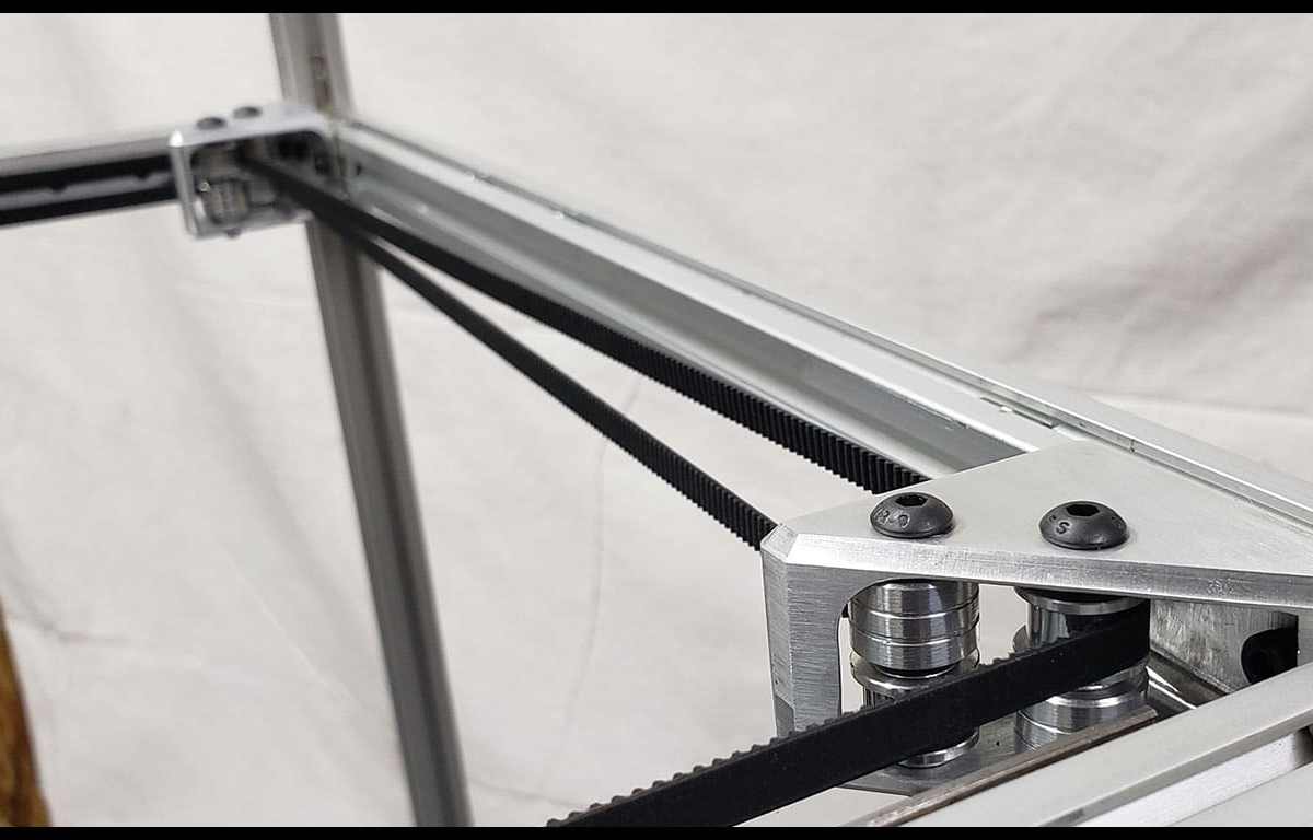
CoreXY Belt Routing
CoreXY Belt Routing One of the most important parts for corexy movement is belt routing. Here’s a guide to the mechanics of corexy belt routing pulley layout in order to get accuracy and constant belt tension. Belt Routing Methods There are two main ways to implement the corexy belt path. Either a stacked pulley arrangement…
Read More
Large CoreXY Build-Hardware And Firmware Settings That Increase Performance
CoreXY Scalability The scalability of a core-xy printer can be an issue when it comes to hardware design and implementation. An increased belt path can also introduce problems resulting in artifacts in 3d printed parts. A rigid gantry setup is needed and proper binding is a must. 9mm and 12mm belts are available to account…
Read More
Duet 2 vs Duet 3
While a Duet 3 won’t be replacing the Duet 2 anytime soon, it’s a much more professional electronics board that adds a range of options and functionality to your machine build. Although the Duet 3 may be overkill for most users, these options are not for everyone you do get much more out of Duet…
Read More

SolidCore CoreXY 3D Printer
Modular Scalable Linear Rails Balanced Carriage Pull Enclosure BOM utilizes most available parts All Metal Parts or 3D Printed Z-Axis: Independent Driven or Shared Belt Routing
Read More